EQMOD Wiring for Sky Watcher Mounts
Dismiss the hand controller and do less to achieve moreA direct connection via an EQDIRECT cable from a computer to the mount
Page Contents
Why
The EQMOD project implements a ASCOM compatible driver for the Sky-Watcher and Orion (same hardware and software) mounts which can communicate directly with the mount. It also provides various additional features and, most importantly, makes the use of SynScan (as an app or software running in the hand controller) unnecessary. This simplifies the workflow by dimensions, for example, the SynScan star alignment is not required anymore.
Some Sky-Watcher mounts, for example the AZ GTI, are equipped with a WiFi interface. The Sky-Watcher AZ GTI, in particular, does not even include a hand controller. The ZWO ASIAIR, and computers can use WiFi as a connection link to such mounts and so communicate over the EQMOD interface using WiFi. This sounds like an attractive idea, unfortunately it works less reliable and efficient for astrophotography than via cable connection. The connection is unstable and guiding produces a lot of errors via WiFi.
The EQMOD interface requires a serial connection between the mount and a computer. The hand controller socket on the mount, and a USB Type B socket on the newer models, for example EQ6-R Pro are used for this. Sky-Watcher does not provide any cables for this. There are a few 3rd-party cables on the market.
The most straightforward way is a connection over USB. The EQMOD development site provides a description for this. Unfortunately, this description is confusing if you are new to the topic. For example, it sounds like you have to use only the chip sets mentioned on the website. Questions keep coming in forums. Moreover, there are similar adapter cables on the market which have the same plugs on both ends, but a completely incompatible wiring. These cables cause irreparable damage to a mount when connected. People who bought such cables complain on forums and make others even more confused what to do. This page tries to clarify the wiring of an adapter.
Wiring
When you look on the mount, the pins on the hand controller socket are numerated from right to left, i.e. the pin 1 is on the right. Pictures in the user guides from Sky-Watcher show the same view. Unfortunately, the wiring diagram on the EQMOD development site shows another view: the plug from the pins’ side without any comments about this.
Large mounts use RJ45 connectors for the connection to a hand controller. Small mounts including AZ GTI use RJ11 connectors.
RJ45 are the same as ones used for LAN connections. RJ11 are the same connectors as used in the land phones. See the article in Wikipedia for details in case of interest.
Recent releases of Sky-Watcher mounts EQ6R-Pro, AZ-GT6, AZ-GT5 are equipped with a USB-B socket. An USB adapter is not needed for these mounts.
There are multiple wires in use, but 3 of the are relevant for the EQMOD connection:
- Ground
- RX (receiving line)
- TX (transmitting line)
Wiring is mentioned in the manuals for mounts. This is a copy of of wiring picture from the Sky-Watcher AZ GTI mount manual: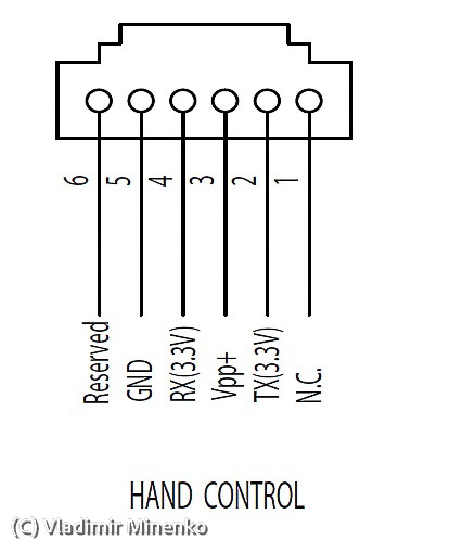
And this is from the Sky-Watcher EQ6-R Pro mount manual:
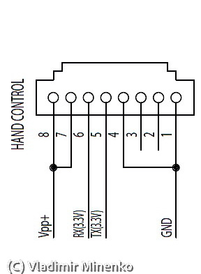
It is important to note that RX and TX lines on the both ends have a crossover connection, i.e. RX on the mount side is connected to TX on the adapter side and vice versa. Connecting RX and TX lines one to one is a popular mistake and is totally harmless.
Another important note. There is a wire with 12V power line to the mount too. This is very important to not swap this one if another, since this will definitely damage something. There are very similar and cheap cables on Internet called “Cisco Console Cable”. These cables have a totally different pin connection which unfortunately least to a damage of the AZ GTI if connected.
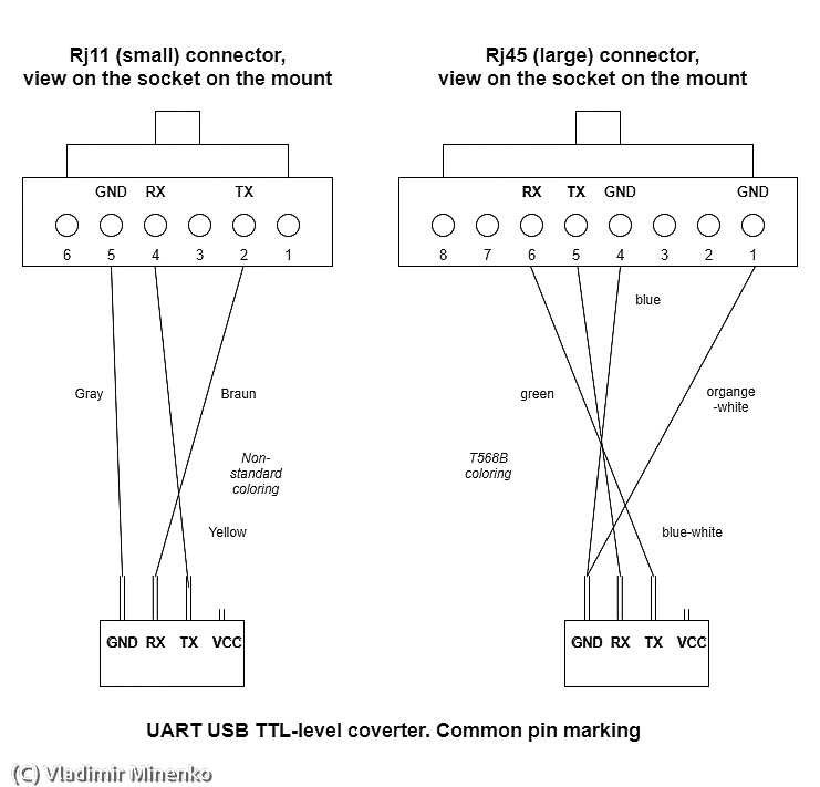
The wiring table is as following (corss-over of RX and TX already considered) :
| USB-TTL lines | RJ11 pin | RJ45 pin |
|---|---|---|
| GND | 5 | 1,4 |
| RX | 2 | 5 |
| TX | 4 | 6 |
This is is the corresponding wiring diagram:
UART USB TTL-Level adapters
Before the rise of micro-computers, like Arduino, building such an adapter on your own was risky, since the market was flooded with cheap adapters based on low quality chip sets. The major reason of problems were two levels of TTL in use – 3.3V and 5.0V. You never knew what you face, and chip sets were not able to automatically adjust. Today, it is safe to buy most adapters if you stay away from very cheap choices from unknown sources. Most modern chip set include automatic switching between 3.3V and 5.0V levels. See this discussion on StackExchange for more details. Buying an adapter from such well-known sellers as Adafruit is a good approach for a start.
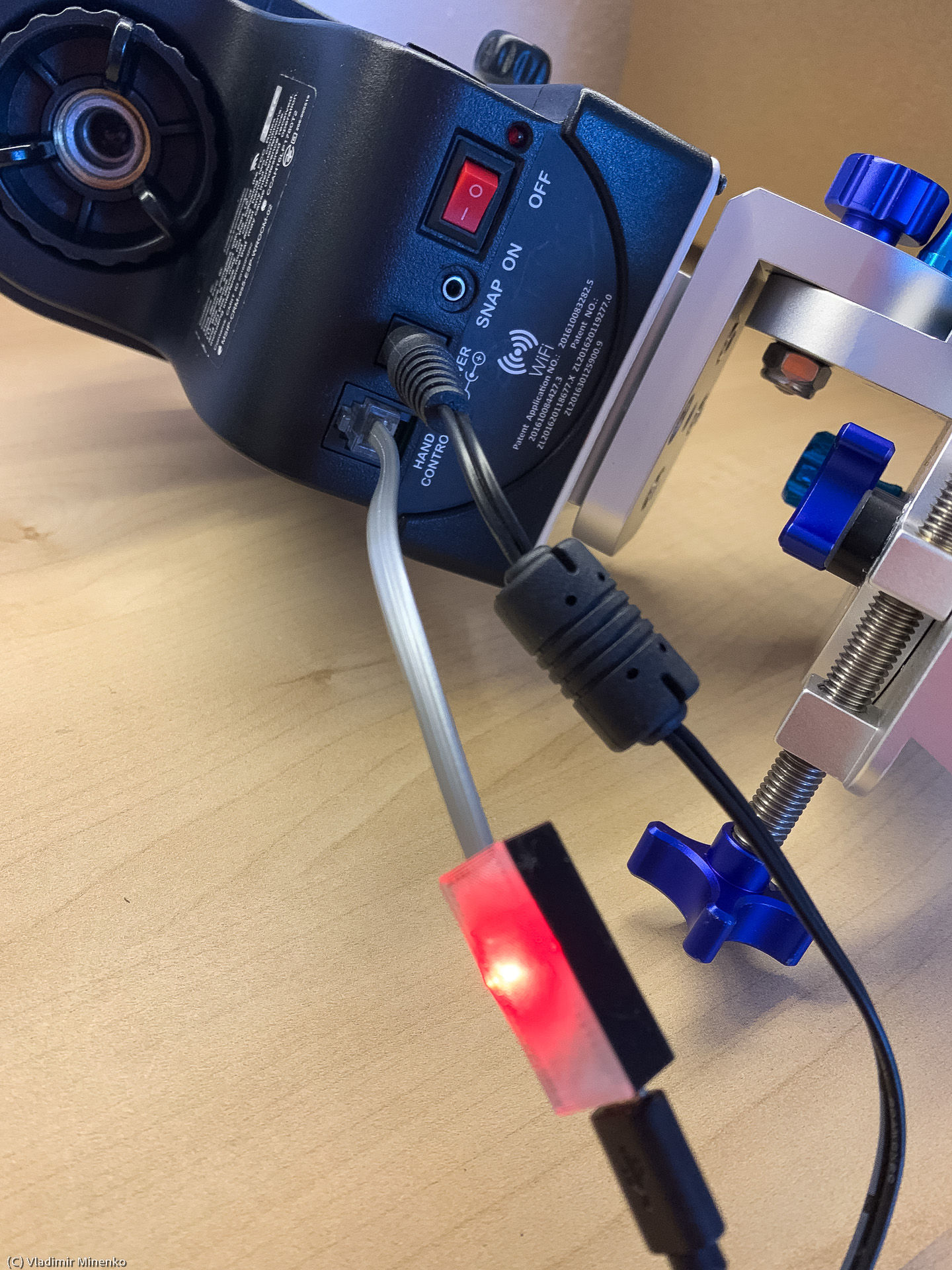
Generally, adapters are available as pre-made cables or modules with headers. I selected the latter choice and found an module which comes with a micro USB socket instead of USB header leads or an USB Type A plug. With this, you can make a small adapter and use it with a cable of any length. In a few adapters I made, I used a module based on the CH340C chip, for example, as sold here and here.
0 Comments