Making a Powered Counterweight
Why carrying two heavy parts?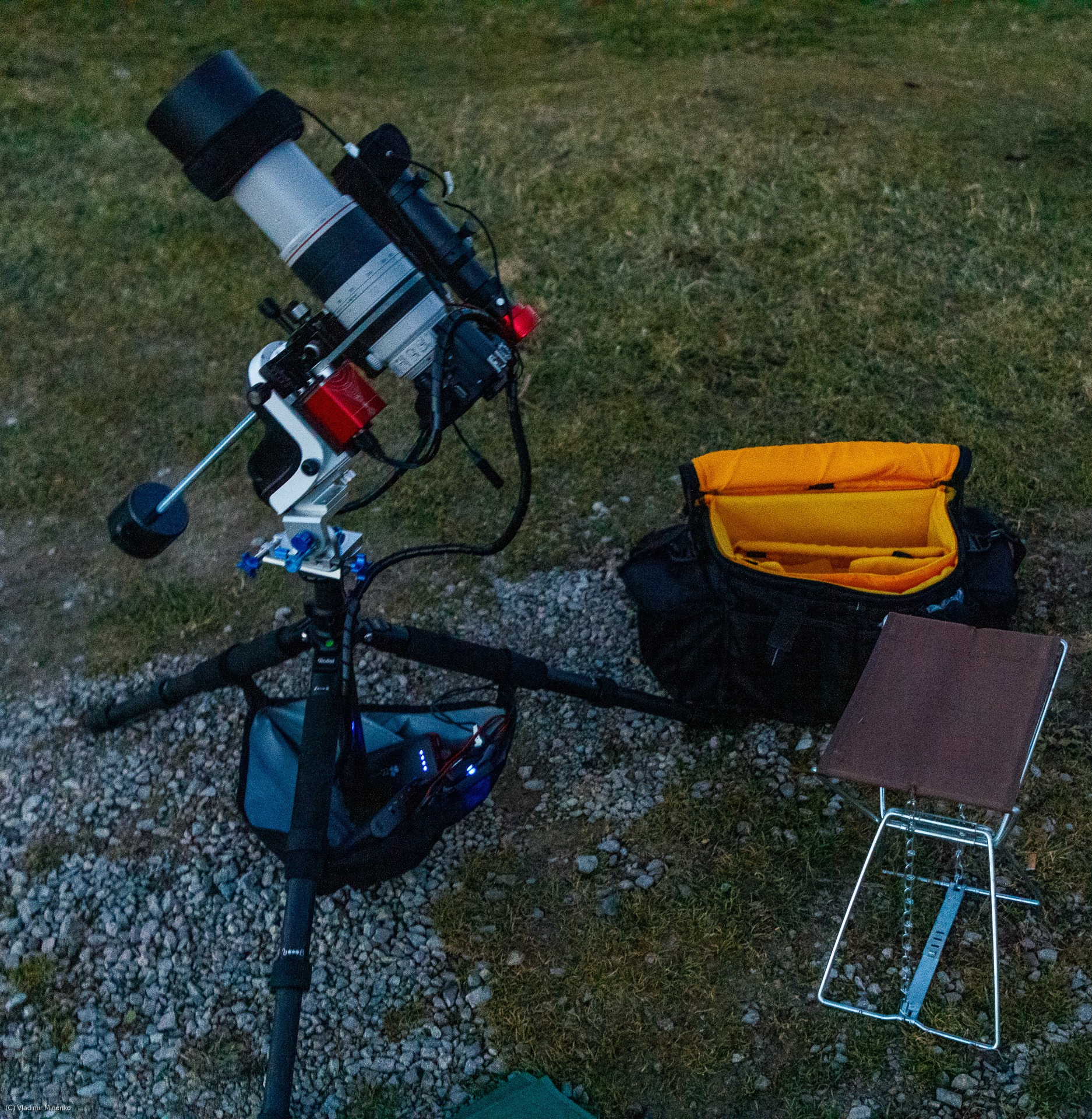
Using equatorial mounts requires using counterweights to achieve a balanced distribution the weight regardless of the rotation of the mount and the sizes of the payload. Counterweights are usually cylindrical and are placed on a bar along the RA axis. Their weight ranges from 1kg to 5kg, sometimes more.
Additionally, a rechargeable battery is needed to power the gear in the field. Even small portable setups consume 10-13W on 12V while tracking, guiding and making pictures. Plus, 6-18W are consumed by dew heaters. 5h in the field require around 150Wh energy. Even with modern battery technology, the cells alone would weight around 1kg.
If you like to have a portable setup which you could carry in a bag, you soon ask yourself, does it make sense to carry two “passive” weights: a counterweight and a battery. Can they be combined?
This idea is not new. iOptron once offered a battery which could be placed on the counterweight bar, called PowerWeight (TM). Its weight was around 3.2kg (7lb). It used lead-acid battery cells and had 98Wh on 12V. The PowerWeight is not on the market anymore, and some people say it was not reliable. Today, 3.2kg counterweight is too much for portable mounts like Sky-Watcher AZ GTI and 98Wh is not enough even small setups based on such mounts. Unfortunately, there are still no other comparable products on the market. Most people use various power banks and large portable power stations. This causes another awkward circumstance. A lot power cables going down from the mount to the battery. Cables tend to wrap around all parts and become stiff in the cold. This brings gear in a danger and distorts guiding. If a battery is located on the counterweight bar, cables would be much shorter and they would rotate only around one axis passing a much smaller angle.
So, lets rewind and revive this idea and create a new implementation based on on modern design and components.
Features on the wish list
Coupe with the battery capacity allowance on civil flights
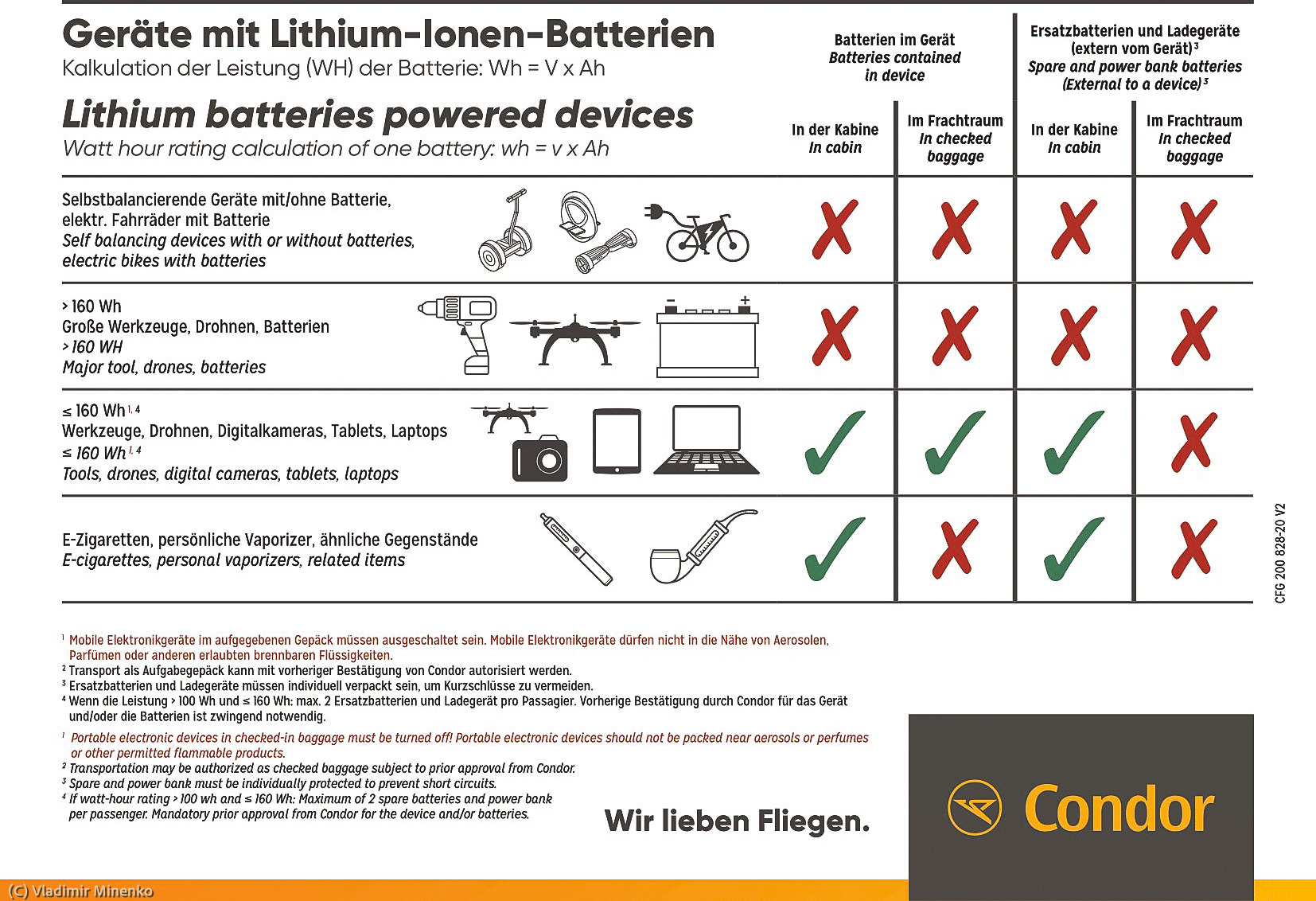
No doubts, a battery has always not enough power, but… After problems with overheated batteries in Samsung smartphones and other portable devices some years ago, there are regulations in place limiting the energy of batteries which can be taken on a regular flight. Despite of the fact that all batteries larger than 2.7Wh have to be carried in the carry-in luggage, the are limits on their capacity in total. You can take batteries with not more then than 100Wh without additional administrative hassle. Batteries with more than 100Wh, but not larger than 160Wh have to be approved by the airline. Not more than two of such batteries can be taken on board. All batteries should be for own use. At the end, it is all about the amount of Lithium you take on board.
The above regulation is focused on large spare batteries and devices with such batteries. It is not defined if several smaller batteries are OK, but a reasonable amount should be OK, if their purpose can be explained. It is also not documented how to approve larger batteries.
So, it is a good idea to be flexible with number of battery cells used. It should be possible to transport them separately. We still want to achieve 200-250Wh energy reserve when not transported by planes. 200W would provide 40W for 5h which is sufficient in most cases.
Battery cells availability
We want to use battery cells which widely available. This fact also affects the battery in scope. Lithium-ion polymer battery cells currently dominate the market. Almost all power banks and many other devices use the 18650 cells (see an overview in this article even though it is not so apparent. There is a vast amount of Brands and models. 18650 cells are available almost anywhere.
Lithium iron phosphate batteries, also know as just “LiFePo4” or “LFP” seem to be a new rising star, but they are not widely available and do not have widely known standard sizes. Most LiFePo4 cells are often used in electric scooters, power walls and solar energy storage. Due to this, cells are provided in large capacity, but also in a large size. They are screwed or welded in packs of four. This means it will be hard to handle them separately. Their unusual form factor will attract a high attention during security checks in airports.
The key advantage of using high-capacity LiFePo4 cells is that less safety measures are needed, since it is not needed to connected cells in parallel to reach a higher capacity. In this case the BMS module can detect dangerous state of each cell. Smaller 18650 cells have to be connected parallel to achieve a higher total capacity. In this case either a protection circuit or a “fuse wire” MUST BE USED to make sure that a cell is cut off if it has problems.
Most larger LiFePo4 cells have the form of a brick with various side dimensions. It seems that there is no unified (not speaking of a standard) size of these batteries. A lot of 30Ah cells are offered AliExpress. This is probably because the are convenient to upgrade the old lead-acid batteries in electric scooters in Asia to the new battery technology 😉
Liitokala, Small Den, and VariCore, Mr.Li Battery are popular seller on https://aliexpress.com.
These are frequently seen and most interesting form factors of LiFePO cells for our use case:
- 32700 – cylindrical cell, 32mm x 70mm, 6500mAh, the weight is around 145g
- 33140 – cylindrical cell, 33mm x 140mm, 15Ah, the weight is around 270g
- 38120 – cylindrical cell, 38mm x 120mm, 10Ah, the weight is around 340g
- 24Ah/25Ah – brick-formed cells, 132mm x 72mm x 28mm, 24Ah, around 530g
- 30Ah or 50Ah – brick-formed cells with larger dimensions
For now, we take the 18650 cells.
Charging
For charging, we should target 12V voltage which is de-factor standard in addition to 5V. 12V allows portable charging from other power stations and in a car. Charging on 12V is not available with most portable batteries with 12V output, since it requites a constant current power supply with a step-up converter. The device should have an integrated power supply so that it will be enough to plug a 12V power cord with sufficient power.
Consumed power
We target to provide around 40W (3.3A on 12V) for around 5h. This should be sufficient for a larger rig running non-stop for 4.5h dark time.
Cell layout
We have to decide how many cells will be connected parallel in a group and how many of such groups connected in series we need.
Nominal output voltage of a 18650 cell is 3.70V. Connecting three groups we will get 11.10V and connecting four groups we will get 14.80V. The voltage at 0% capacity is around 3.00V and at 100% is 4.2V. So with three groups, we have 9.00-12.60V and with four – 12.00-16.8V. In either of the cases we need a step-up or step-down voltage converter to provide constant 12V output.
The number of cells in a group defines the capacity per group. Since do not want to exceed limits of amount of Lithium in batteries on planes, it makes sense to use three groups and use a step-up converter, since this will require less cells in total per 1W power on 12V.
Battery Management System vs Protection Board
Charging of either LiFePo4 or LiPo batteries requites a special circuit. For power output of more than 5V, two or more cells are connected in series. Charging of multiple cells in series requires a control of the level of charging of each of the cells. In the course of last years, it became a real research topic how exactly this is done and what are the best approaches for this.
There is a large choice of pre-made modules this purpose. Better ones implement a Battery Management System and simpler ones just provide a basic protection. The price and size difference between these categories is almost negligible in our use case. Today, it definitely makes sense to use a BMS module. Those contain one or two micro-controllers in a addition to several MOSFET on the board.
Monitoring
Basic monitoring is required. We want to know how much power is left. Ee wish to see this value in not on an LED bars as as a Watt number, but ideally in hours and minutes. A device measuring power is called in electronic watt-meter, but we actually want to use a coulombmeter – a device for measuring electric charge. In most cases, these devices look the same and are connected in the same way, but coulombmeter devices show additional information, such a remaining capacity and sometimes remaining running time.
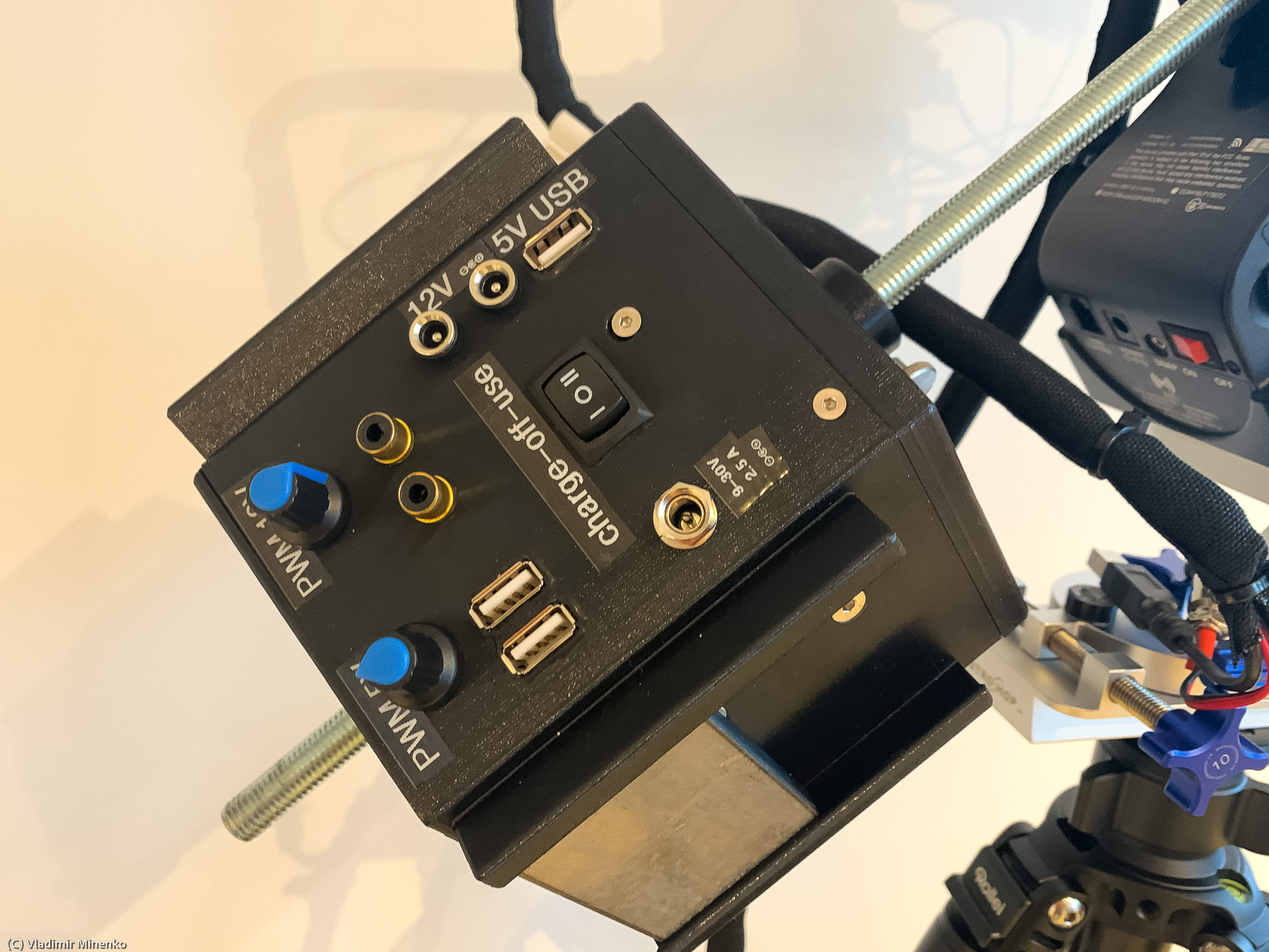
Connectors and output voltages
12V is a standard voltage in astrophotography. Sometimes 5V is used for additional devices. There is no unified plug for 12V on astrophotography mounts. Coaxial 5.5mm × 2.1mm power connectors see to be most popular though. Dew heaters use either RCA connectors or USB connectors driven by a PWM controller to vary the heating power.
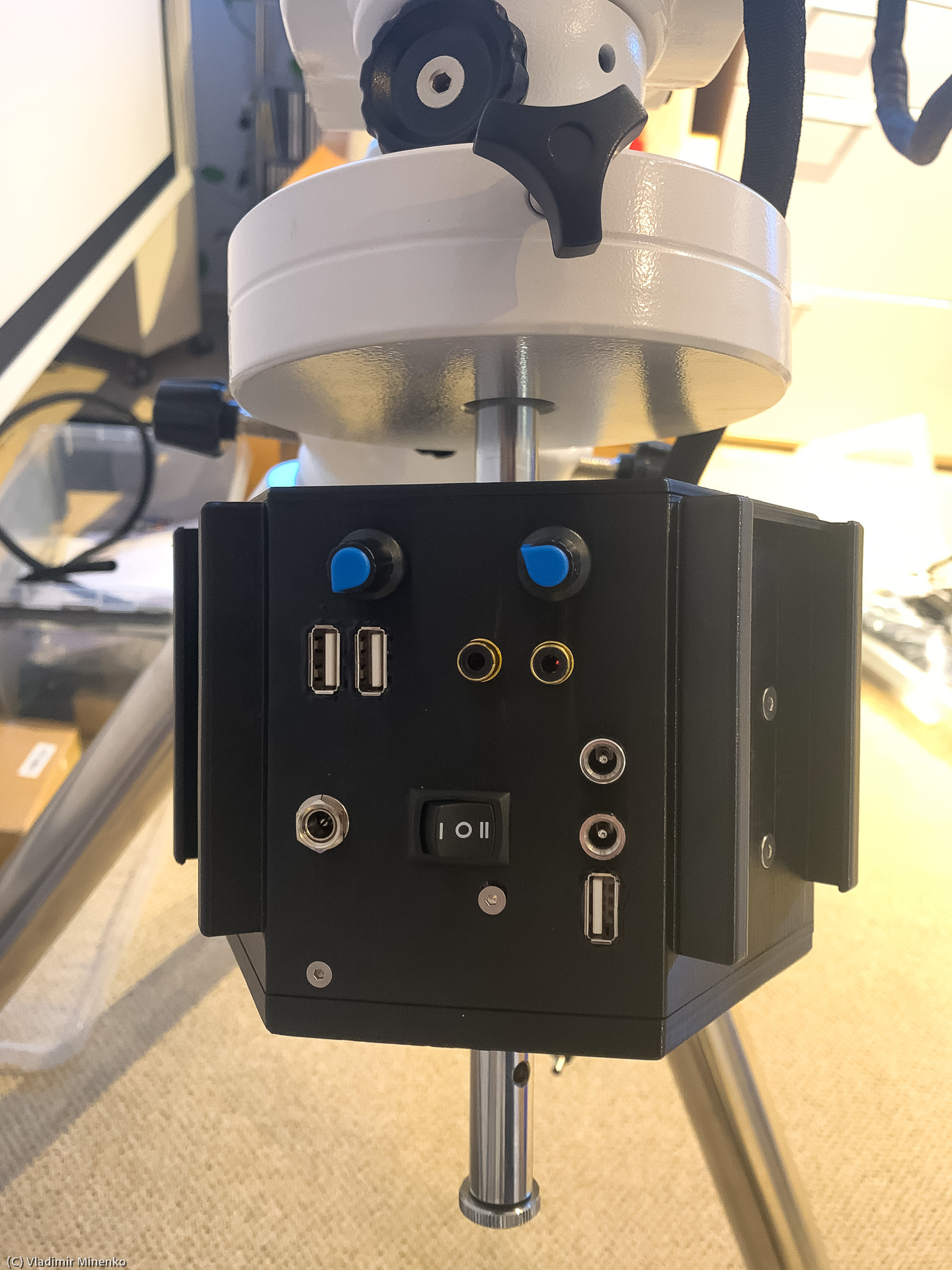
It is a good idea to power the mount on a separate line, since if power is lost, all time, location and star alignment (if still used) settings should be reinitialized. So we will need two 12V connectors. Often, two dew heaters are needed, one for the main scope and one for the guide scope.
Casing Symmetry
The case of a powered counter weight should definitely show some symmetry around the center axis.
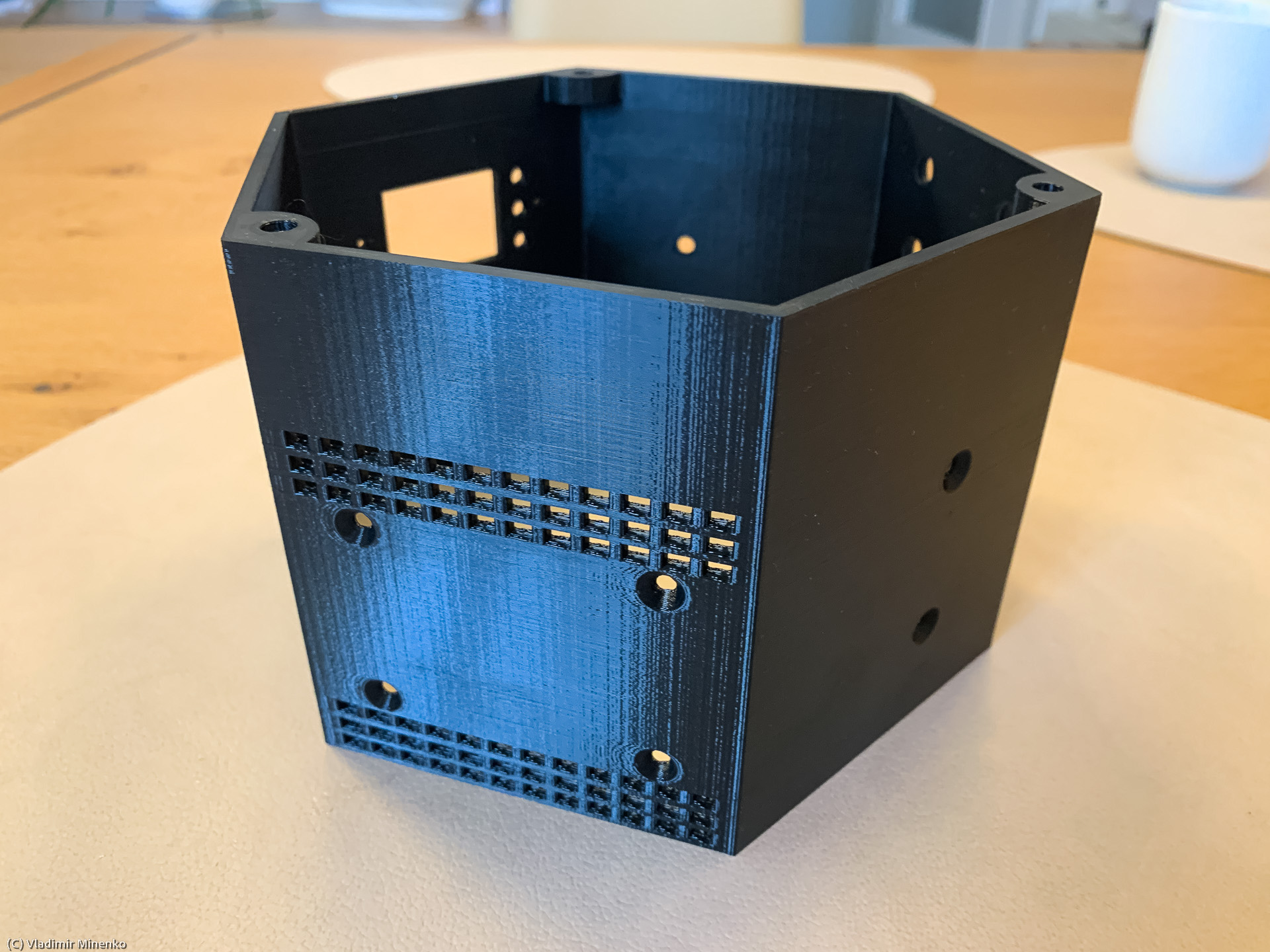
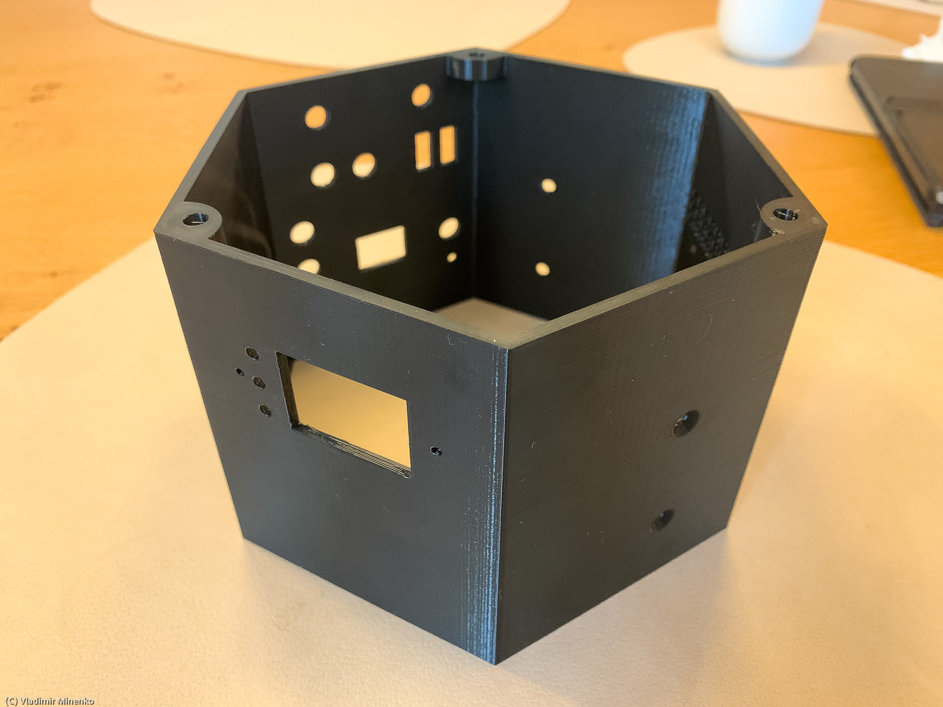
This is not a simple aspect, since we want to have a reasonable size and accommodate quite some electronics in inside the casing. In several placing experiments Fusion 360, it turned out that large cylindrical cells are the worst choice for a casing with these criteria. Brick-formed cells are better, since their form can be well aligned with electronic modules. 18650 cells can be placed in the most flexible way, but this requires a lot of detailed work in 3D design.
Counterweight bar diameter
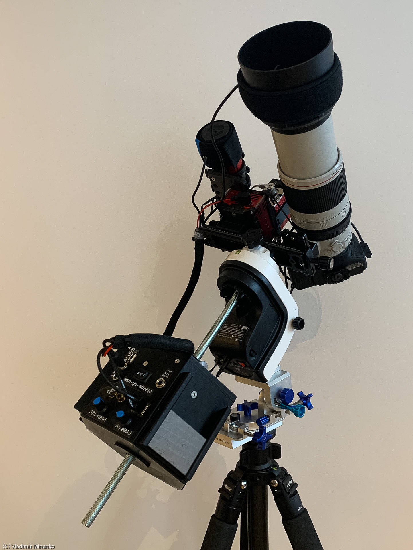
We want to be able to use the new counterweight in various counterweight bars with a universal mount. The diameter of counterweight bar is another element in astronomy equipment which escaped any standards. It ranges from 12mm to 38mm.
Resulting and anticipated weight
I’m currently using a 2kg counterweight with my Sky-Watcher AZ GTI loaded with around 3.5kg gear. It has to be placed far far away on the bar which is not so good. The weight of one 18650 cell is around 46g. If we use 18 cells providing 233,10Wh energy, the total weight of cells will be 830g. Electronics and casing will not be more than 200-300g. So we want to get closer to 2kg, we might need to attach additional weights. Round weights with centered holes of different sizes is not something you get off the shelf…
The Implemented Design
Battery cells and configuration
Three groups of six 18650 cell each are used. This is so-called 3S6P battery pack configuration – 3 serial, 6 parallel. The used cells are Samsung INR 18650-35E. In this configuration, the whole battery pack provides 21mAh capacity and 233.1Wh energy on 12v.
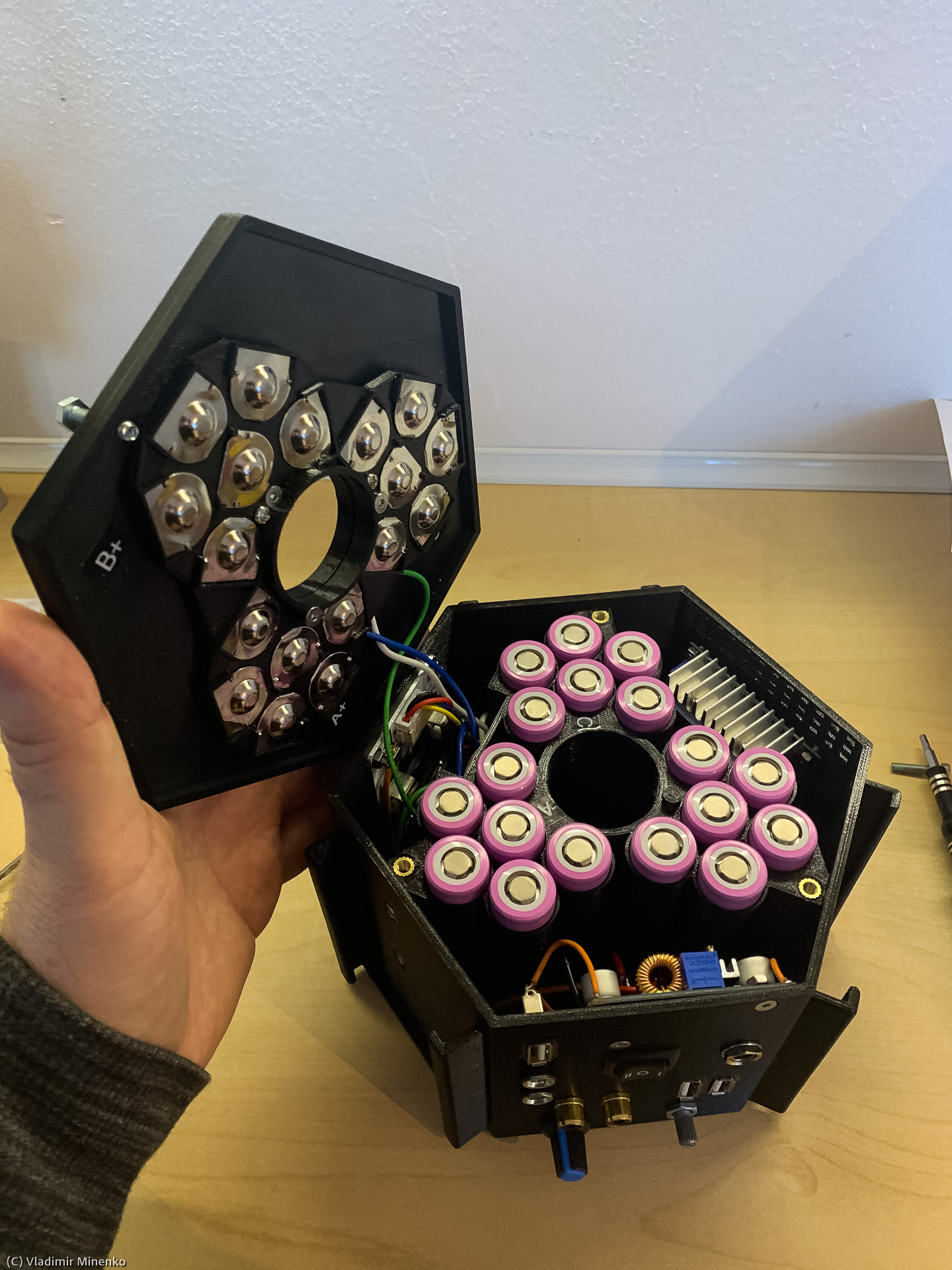
Unlike quite some projects on the internet, the cells ion the parallel groups are secured with a fuse wire. A 0.2mm copper wire holds up to 5A load. This would result in 30A total current which far above the protection limits in the used converts. But 5A is below the max current per cells and so far below the emergency current.
Casing
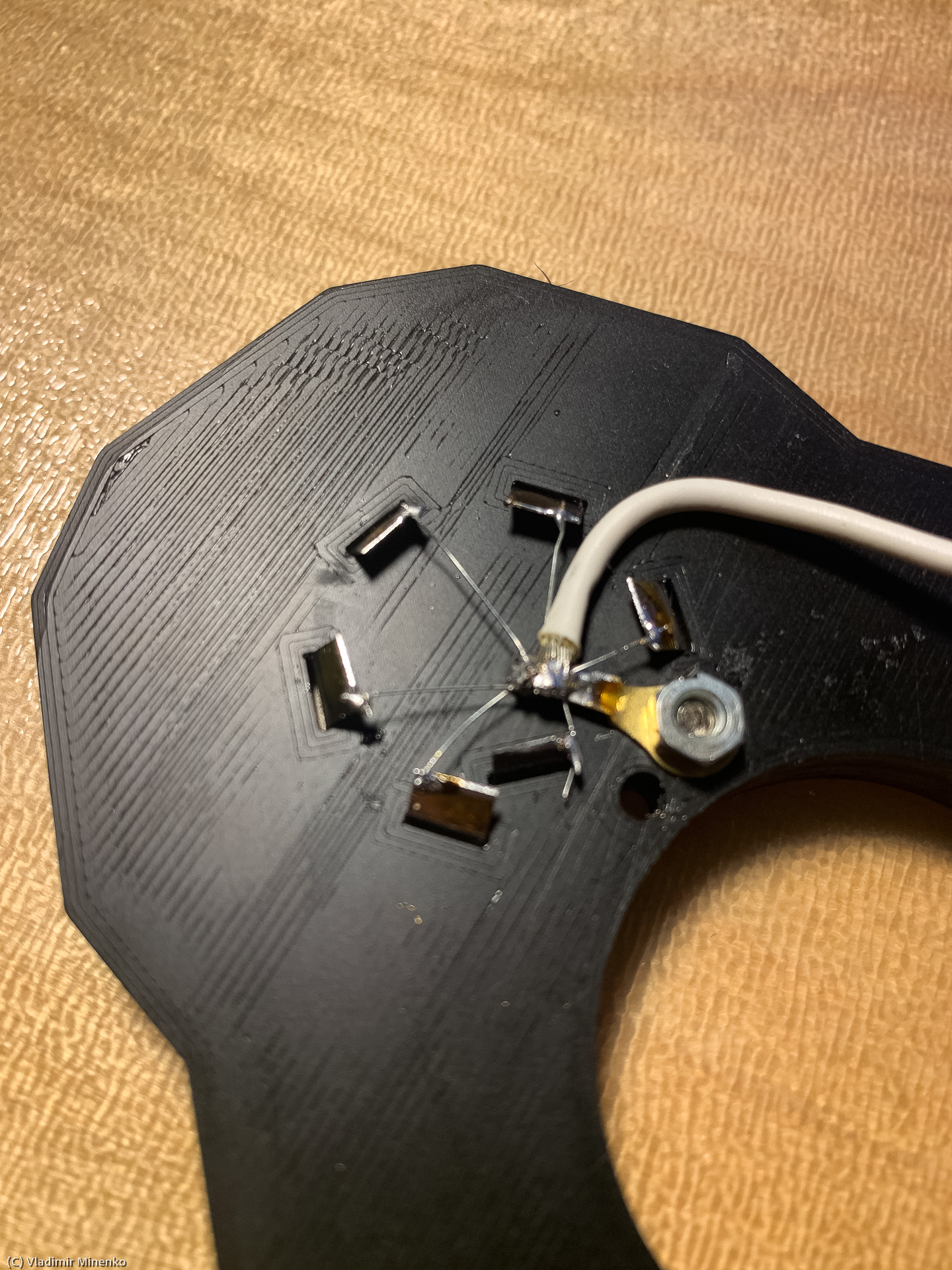
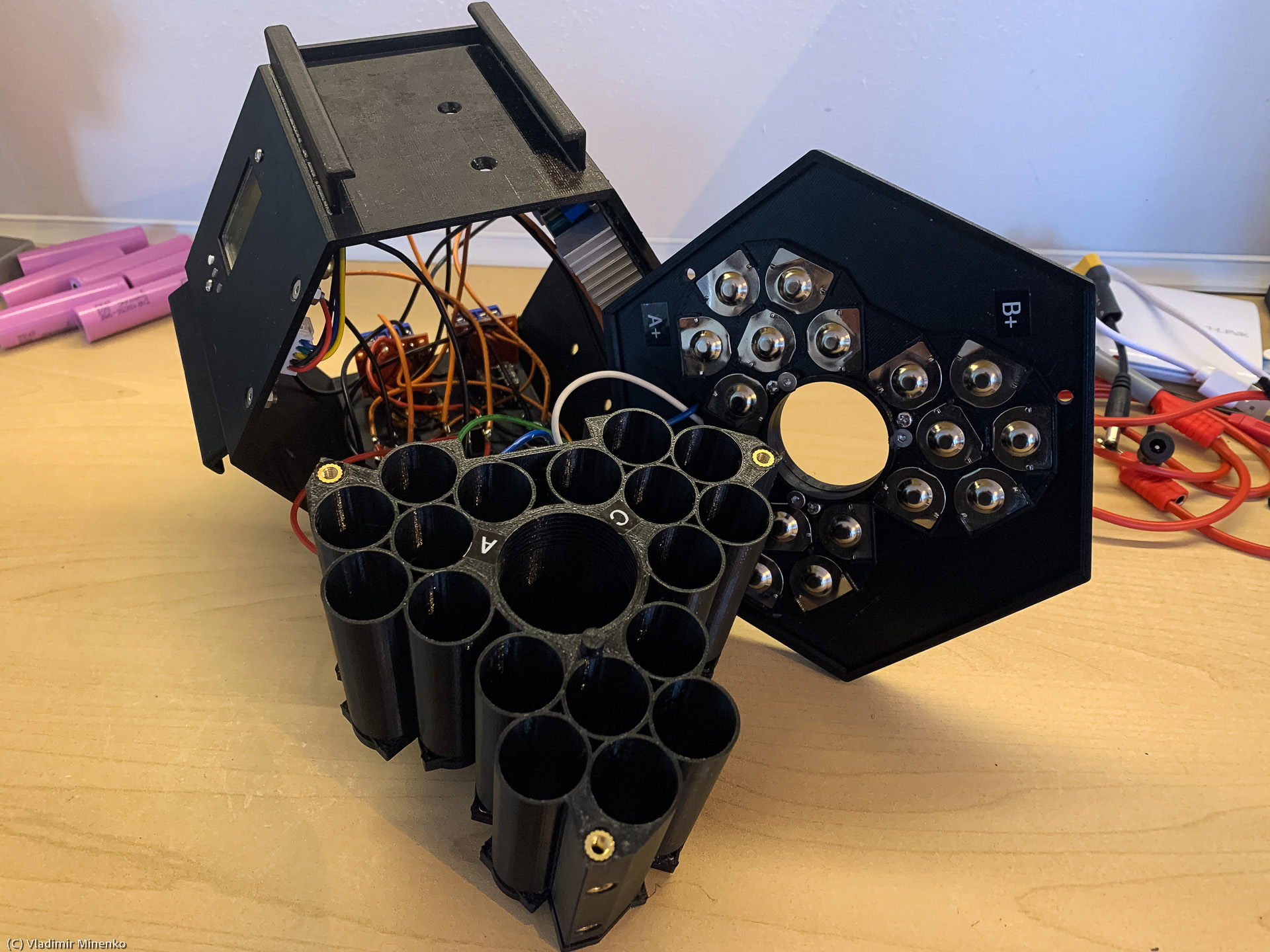
The key idea of the casing construction was to have a central cylinder enclosing the counterweight bar of different diameters. A counterweight bar is centered inside the cylinder by two adapters. Adapters are screwed into the casing and can be fit different diameters of the counterweight bar.
Tree groups of the 18650 cells are placed in tree segments of hexagon-shaped casing:
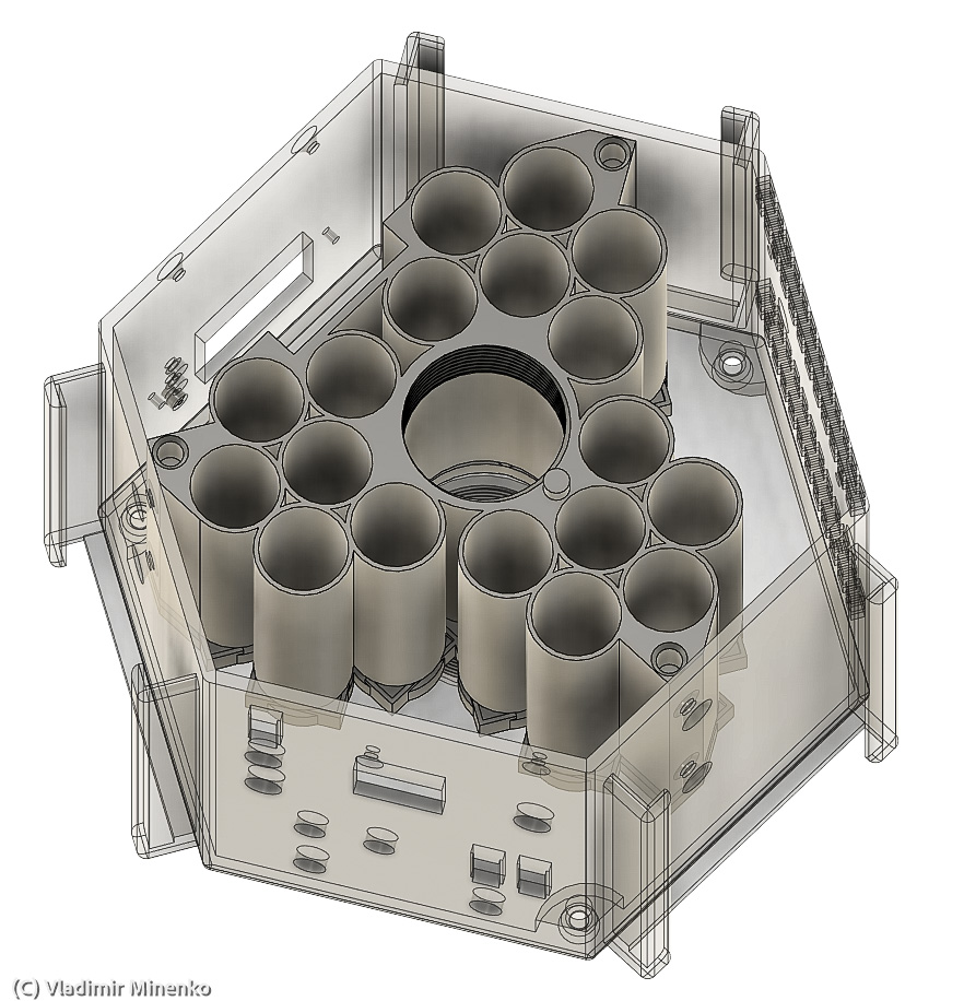
Three remaining segments and the top compartment provide space for electronics. The bottom casing cover holds battery cells.
After the first revision, three holders for iron plates as additional weights have been added, since the total weight was not large enough for a counter weight.
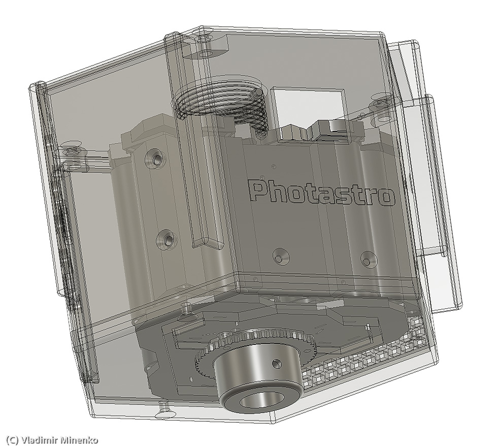
Electronics
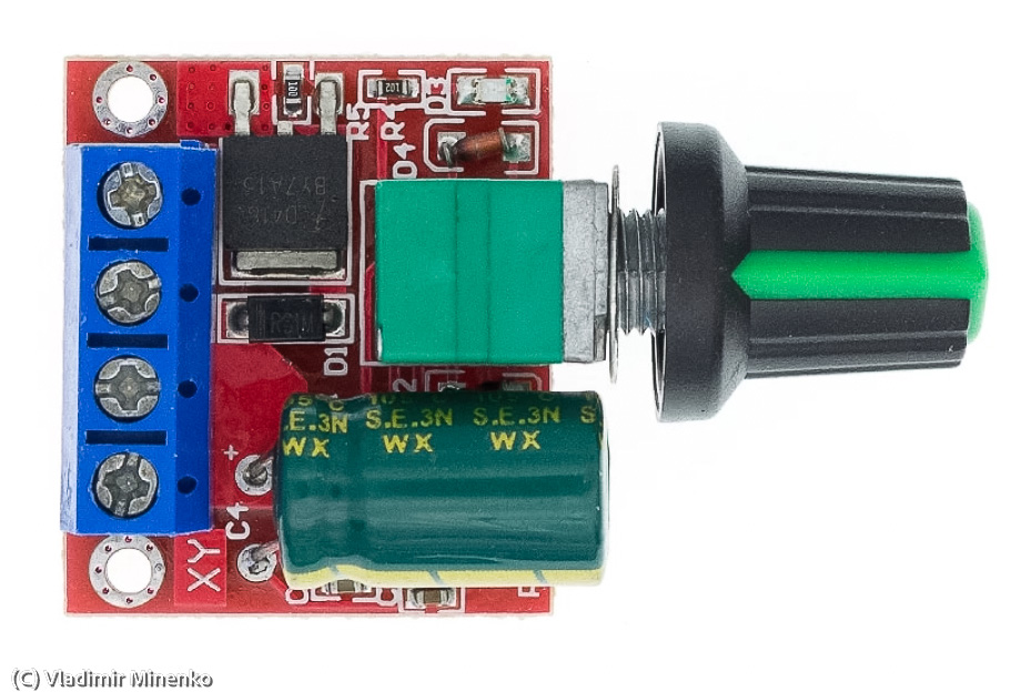
The entire schematics is based on several off-stock modules. The powered counterweight includes an integrated charger module:
- 8A, 5-30V to 1.25-30V adjustable step up down converter, similar to https://www.ebay.de/itm/293493632801
This module allows using any external power supply providing sufficient power for charging. The charging current is currently set to 2.5A.
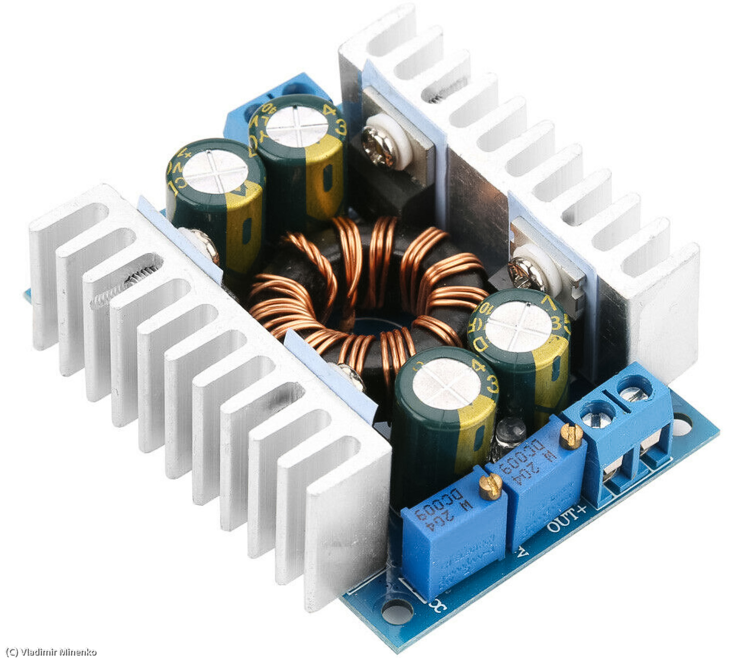
This allows charging of all cells in around 8h without a too height heat desperation inside the case.
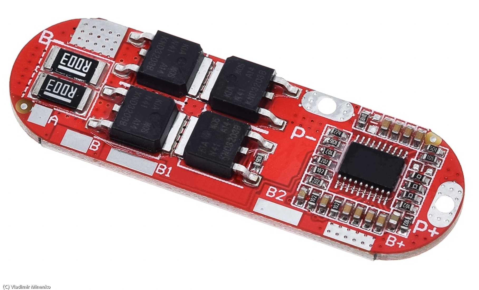
The charging is controlled by the BMS module:
- 3S 10A BMS, similar to https://www.aliexpress.com/item/1005001327267228.html
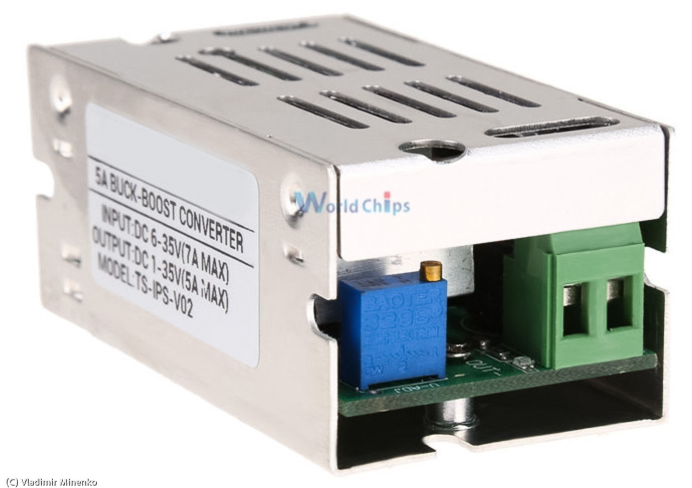
The 12V channel is stabilized by a buck-boost voltage converter:
- 5A, 6-35V to 1-35V adjustable step-up, -down converter, similar to https://www.aliexpress.com/item/32857822288.html
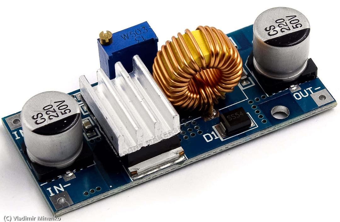
The 5V channel on USB plugs is stabilized by a step-down voltage converter connected directly to the battery:
- XL4015 4-38V to 1.25-36V, 5A adjustable step-up, -down converter, similar to https://www.ebay.de/itm/353352640283
The dew heaters can be connected to either 5V on USB plugs or to 12V. The heating is controlled by PWM controllers:
- Mini DC-DC 4.5V-35V 5A 90W PWM DC motor speed controller, similar to https://www.ebay.de/itm/313583203337
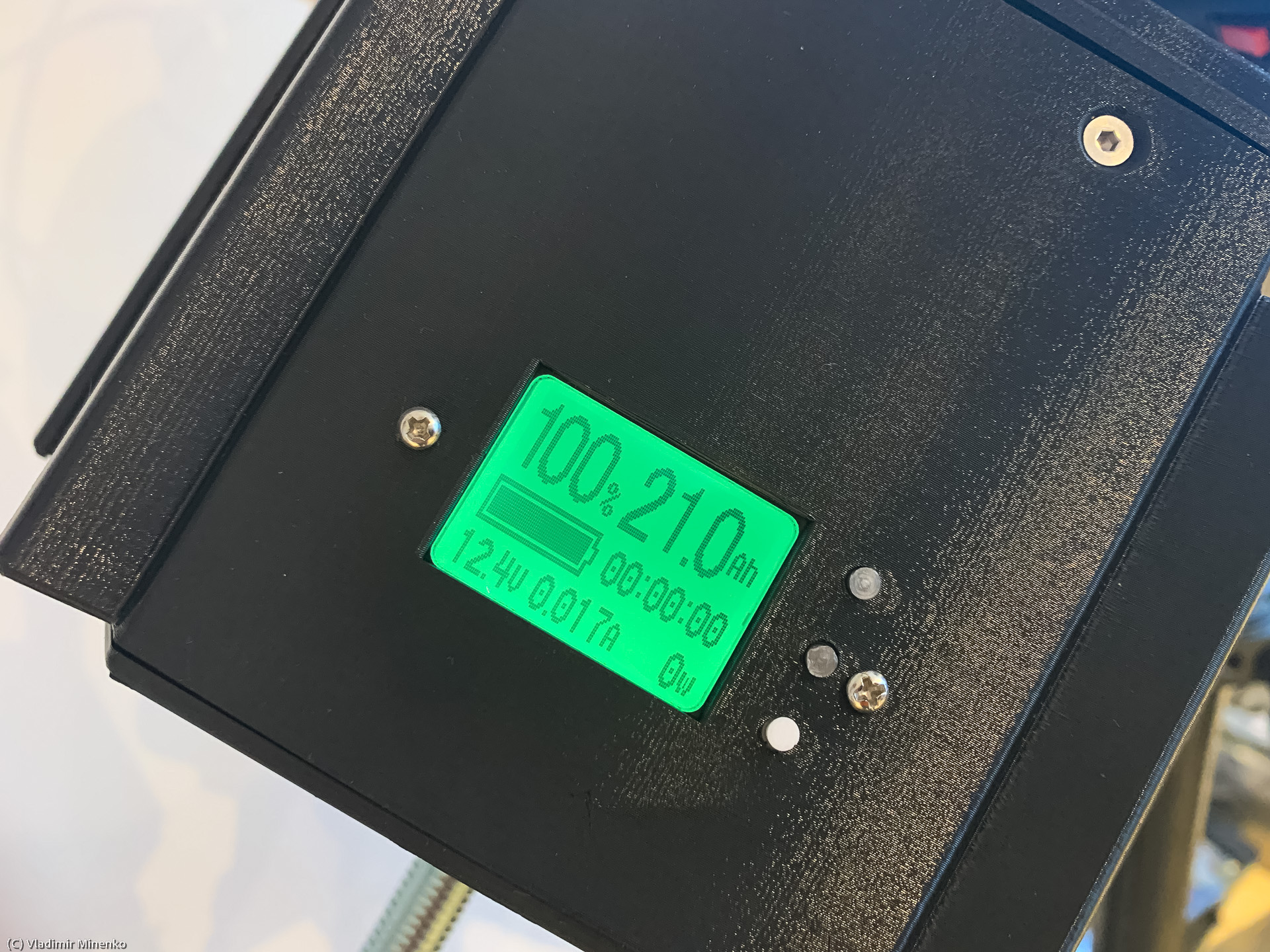
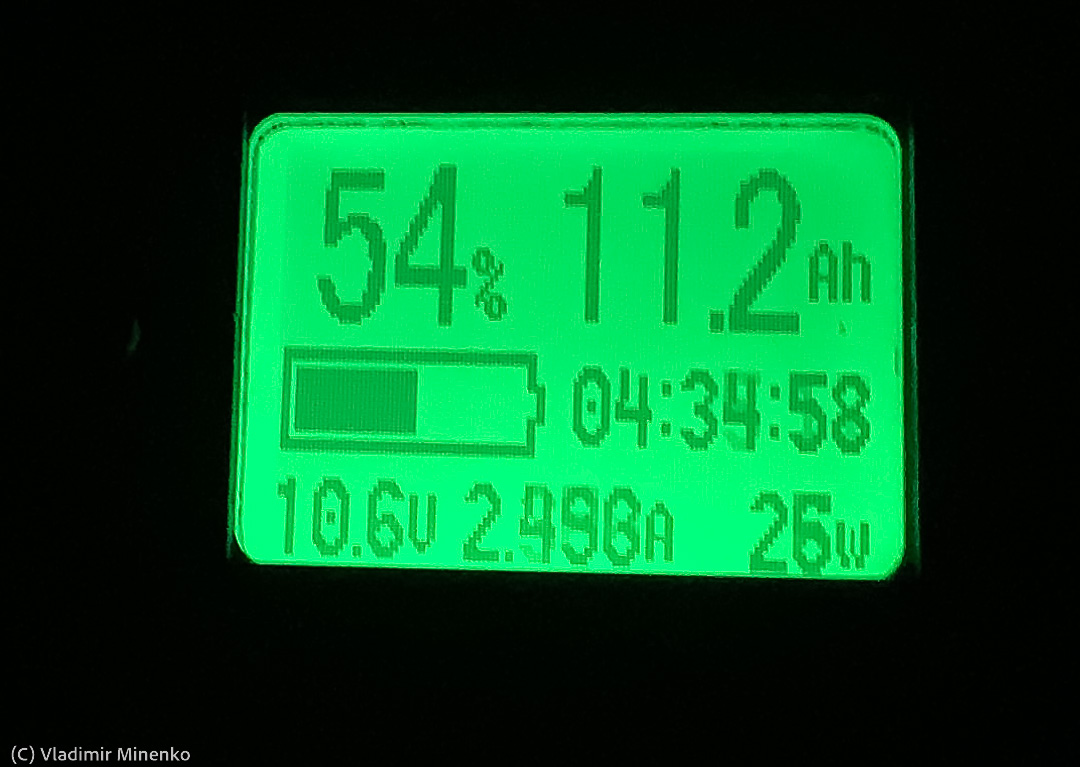
The available capacity, the current consumption and the remaining time can be controlled on the display of the coulombmeter module:
- TK15 8-100V 50A coulombmeter. It is widely available, for example here https://www.aliexpress.com/item/32953547248.html
TK15 is almost unique since it shows the remaining time calculated from the remaining capacity and the average power consumption. This required a few setup steps documented in the manual.
Assembly and the firs time on
It turned out that the assembly of the block is anything else than fast. Fuse protection of the cells, combined with installing spring contact plates (https://www.ebay.de/itm/154001156329) required a lot of time.
There is not much space available inside the casing for comfortable work. A few wires de-touched from the soldering spots due to differences of a low quality of the tin-solder used on the modules.
Following other small parts have been used:
- USB plugs: https://www.ebay.de/itm/282222588586
- DC 5.5/2.1mm plugs: https://www.ebay.de/itm/184232484546
It was a bit confusing to realize that the BMS does not turn on after switching it on for the first time. It needs either a charging power or a load to “activate”. Apparently, is the case for most BMS, but the make it hard to identify the difference between a problem in wiring and missing activation.
Ideas for Some Better Designs
Based on the experience, it make sense to implement following changes in a future design:
- Modular casing with a completely removable electronics board
- Ideally one electronics board with all functional components on it
- Try to use brick-formed cells, but then use them of a much larger capacity
- Replace fuse wires by mini protection board combined with modular cell holders
- Enlarge the capacity to reach the total running time of around 8h on 40W
The Samsung INR18650-35E seem to be of a very good quality with low variation. Another good candidate is Panasonic NCR18650PF. These cells have a slightly lower capacity, but are available for a lower price again and again.
Availability
The STL files for 3D printing are available in the Photastro shop as a free download.
Here are some additional hints for assembly and information about other required mechanical parts (TBD).
Comments
Got an opinion on this topic or found a mistake? Please add a comment.
0 Comments